Someone has said that a relay is like a worker who is tasked with doing a level of work beyond their ability but who gets it done by tapping on a friend's shoulder and having them do the hard work (hmm, sounds like a boss...). A relay is definitely like that. It uses the signal coming in on what would potentially be an overloaded circuit to simply trigger a secondary circuit more capable of carrying the load. That is doubtless where the name "relay" comes from. It's reminiscent of a relay race wherein one runner passes the baton to the next one.
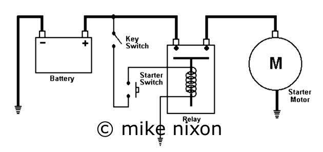
In powersports, the classic and perhaps easiest to visualize use of an electrical relay is in your electric starting circuit. Due to its huge requirement for electrical power (an amazing 1000+ watts), an Asian bike's electric starter draws from its battery between 80 and 120 amps of electric current. That is so much electrical rush that the poor little handlebar's starter button would be instantly fried if it had to carry it; the size of of contacts limits its electrical ability to below 10 amps. Pretty big difference. And I have seen firsthand what happens when a button is overloaded. The spring turns into a molten blob and the button's contacts permanently weld together. Not pretty. Thus we have starter solenoids. The starter solenoid, simply a heavy duty relay, takes the start button's signal and uses it to connect the battery and starter motor electrically independent from the button. Neat.
So in practical terms and in the use we are going to focus on here, the relay's job is to allow one circuit to trigger another circuit to do something too hard for the first one. Powersports manufacturers have used relays for a long time, in circuits other than the electric starter circuit. Yamaha was at one time famous for having a lot of relays on its bikes, but today all the big five brands have many relays on their products, for everything from headlight control to fuel injection power, and of course as the basis of all the safety circuits found on motorcycles today. And there are a lot of them. What we want to talk about in this article is just how relays are used in vintage Asian motorcycle maintenance and modification. Relays are used in many ways for a variety of reasons, but for this article, we'll focus on just this "handing off" function.
Let's think about electrical connectors for a minute. Unlike those on today's vehicles, vintage motorcycle electrical connectors have no seals to ward off dirt and moisture. So they are prone to building up dirt and corrosion that makes them also increase in their electrical resistance. That is, their ability to conduct voltage gradually decreases with age. But even when these connectors were brand new, and even today's rubber sealed connectors, have a little-known and inevitable characteristic of absorbing electrical energy. Theoretically, a connector should not use energy but only convey it. But it is universally agreed in the powersports technical world that the reality is we can expect a connector to absorb up to 0.2 volts, after which we call it a problem and before which we do not. By itself, that is not very significant. The problem arises when we consider that few circuits on your bike have only one connector. Even the horn, the simplest electrical circuit on the bike, is liable to have at least four to five connectors, and a more complex circuit can have twice as many. So do the math. That 0.2 volts multiplied by the number of connectors. Yep. Taking into consideration the connectors, wires, fuse terminals, and switches, even a fairly simple headlight circuit can drop 2-3 volts between the battery and the headlight, resulting in some loss of lighting efficiency, no doubt.
In fact it is this very fact and this very circuit, the headlight circuit, that has user forums all over the 'net buzzing about the fitting of relays in efforts to recover this lost voltage and thus maximize the designed-in lighting potential. It's not a bad idea either.
The optimum way to use a relay to increase headlight efficiency is to add an independent circuit at the battery with its own fuse. But this is electrically messy and not considered best practice in the automotive world. Next optimum and a little neater electrically would be to tap off the bike's mainfuse. From either starting point you would then go through the secondary (load) side of a Bosch style relay and on to the headlight fuse or hi/lo switch, preferably the fuse. For the primary (control) side of the relay, you have two options. If you want headlight on/off control you wire the relay's primary side to your existing headlight on/off switch if you have one, or an auxiliary one if you don't. If no on/off control is needed, then simply wire the relay's primary side to the keyswitch, and the headlight will be on whenever the key is on, as it is in many later model vintage machines.
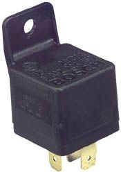
A few thoughts about relays. We are assuming here the ubiquitous Bosch-designed relay having five terminals. This relay is a marvelous piece of work, having the ability to adapt to many kinds of circuits with choices of controlling those circuits in different ways. The user needs therefore to ferret out which terminals to use in your application, but some help is provided below. Beware of "deals" on the Internet for Bosch style relays. Most are made in the far east and are really junk. The original Bosch-made relay is still available but Bosch sold off their relay business some years ago to Tyco, who is now making the "official" Bosch relay in Portugal. Despite this the relay is a much better unit than the ones from China, which melt internally and due to insufficient sealing tend to corrode from outside elements. One of the big four Japanese OEMs recently had a very bad experience with the Chinese product, necessitating the replacement of all the relays on its police bikes. A big deal, as you can imagine.
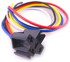
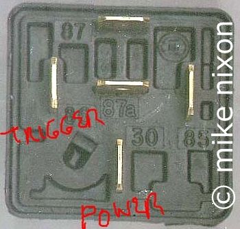
So the basic Bosch relay wiring is as follows On the secondary side, power comes in on terminal 30 and goes out on terminal 87. On the primary side, the controlling ("trigger") voltage comes in on terminal 86 and goes out on terminal 85. Leave the extra 5th (center) terminal (87A) alone. It is used when you want to remotely turn a circuit off instead of turn it on. It is strongly advisable to use one of the many ready-made wiring looms available for the Bosch style relay. If neatens up the installation and provides added terminal protection against the elements.
One more thing. The Bosch pinout design has some logic to it. Note that there is one terminal that is unique in that unlike its brothers it is not parallel to the side of the relay's case. This is a purposeful tipoff to this being the secondary input terminal, that is, terminal 30, considered the main terminal, the one doing all the work. Then opposite terminal 30 is its partner, terminal 87, the secondary side output terminal. The logic continues with the first terminal clockwise from terminal 30, the secondary input, being terminal 86 which is the primary side's input. This leaves terminal 85 (primary output) and you have your four connections.
The basic Bosch terminal pinout. Note terminal 30 is secondary power into the relay, terminal 87 is secondsry power out to the headlight. Terminal 86 is primary power in from a switch, terminal 85 is primary power out to ground. Here's an example of colors for the headlight circuit on most vintage Hondas. Terminal 30 would get red from after the mainfuse, and terminal 87 would get black or black/red (depending on year) before the headlight fuse. On the primary side, terminal 86 would get power from the plain black wire coming out of the keyswitch (assuming no on/off for headlight), and terminal 85 would go to a good ground, preferably right to the battery negative terminal. If your bike has a headlight on/off switch then use it in place of the keyswitch connections.
http://www.motorcycleproject.com/motorc ... elays.html