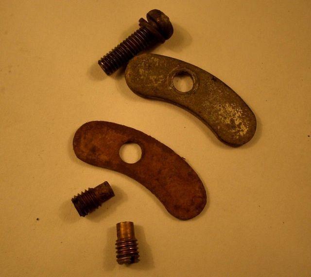
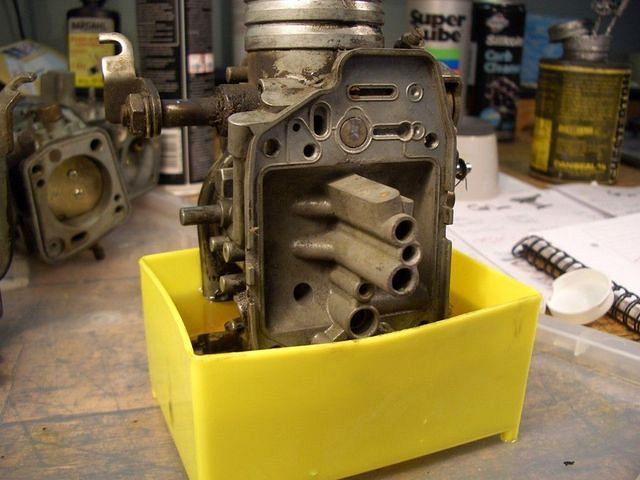
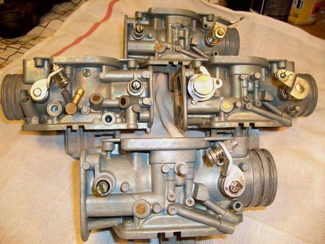
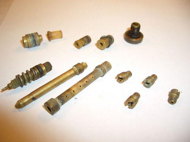
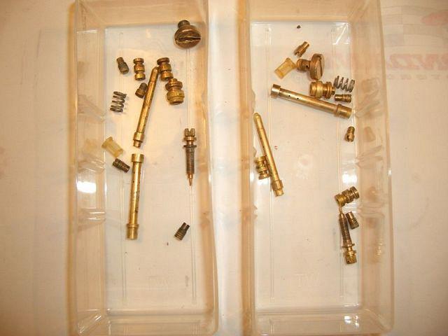
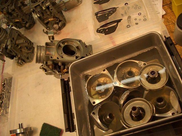
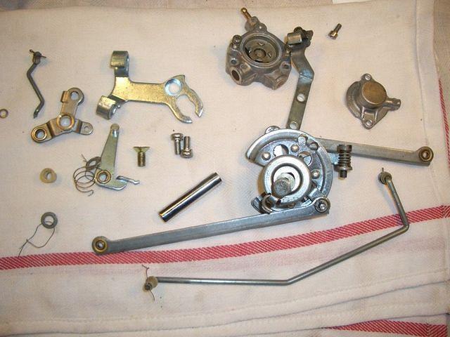
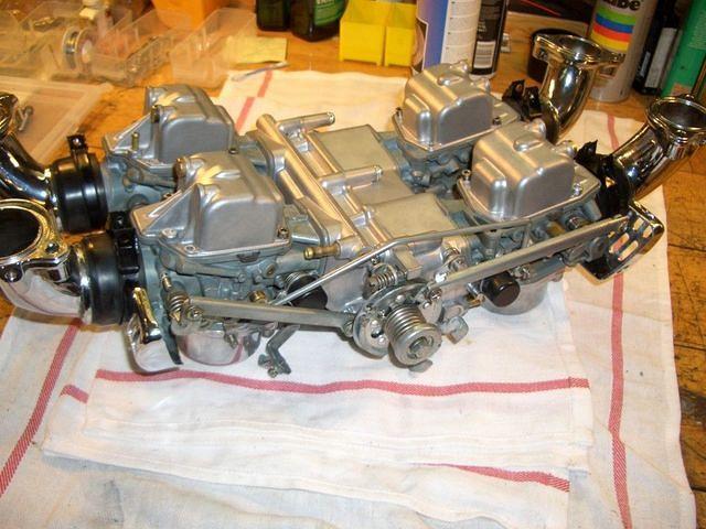
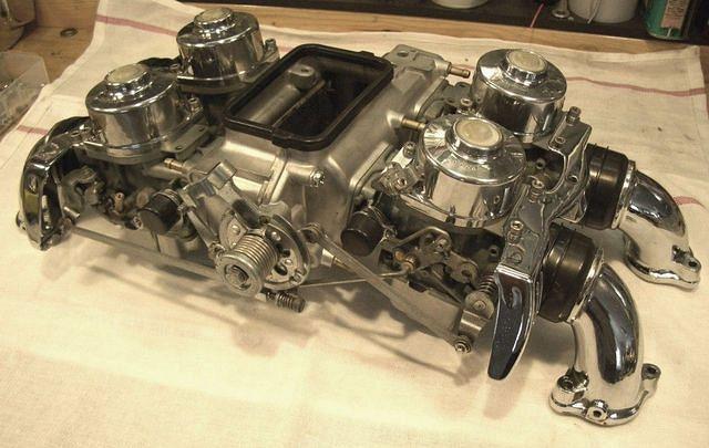
they most probably look something like this..eeek
..or worse
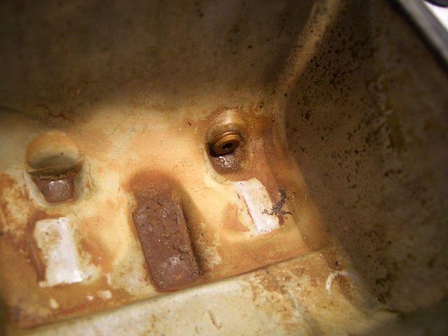
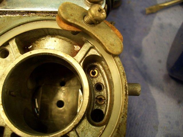
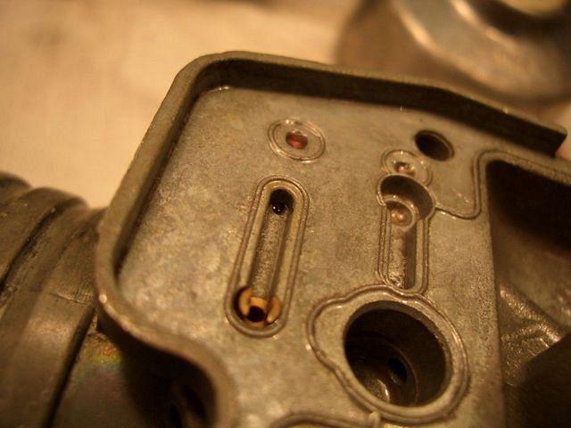
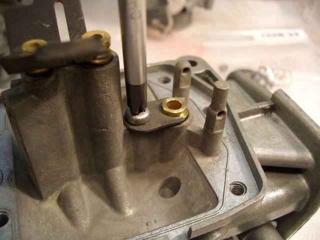
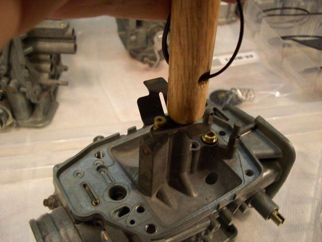
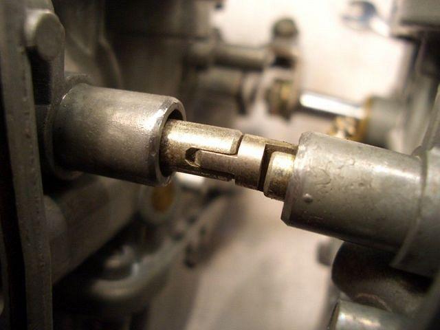
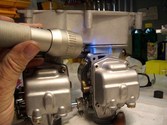
remove float pivot pin
VERY VERY VERY VERY carefully.
It's not uncommon that the 'arms' that holds the pin breaks

I used a sharp...er...none-screwdriver,
and tapped on it ever-so-carefully
..till I could get a grip with a set of plyers
..pulled them out in a STRAIGHT line
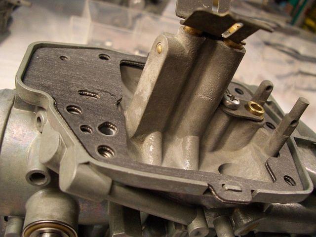
Remove floats.
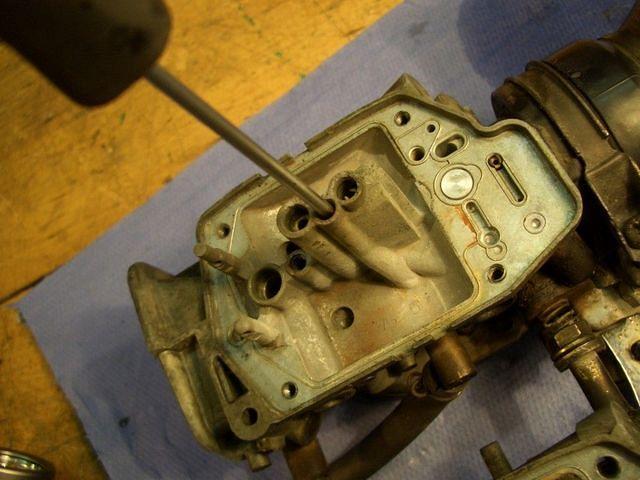
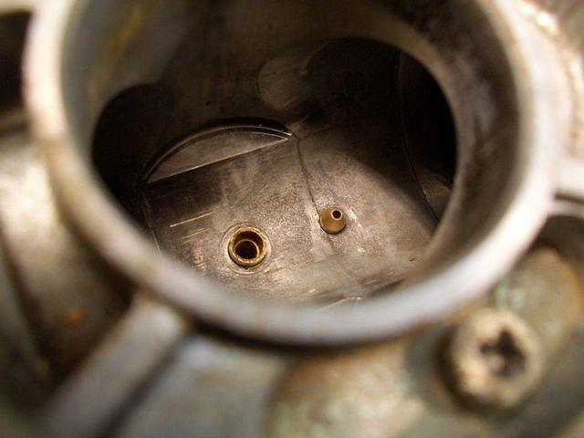
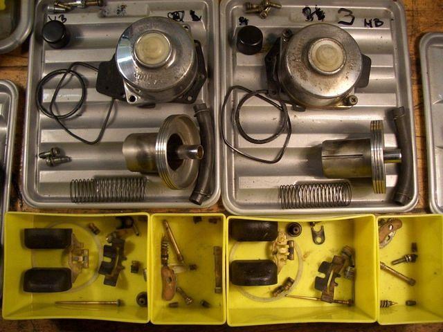
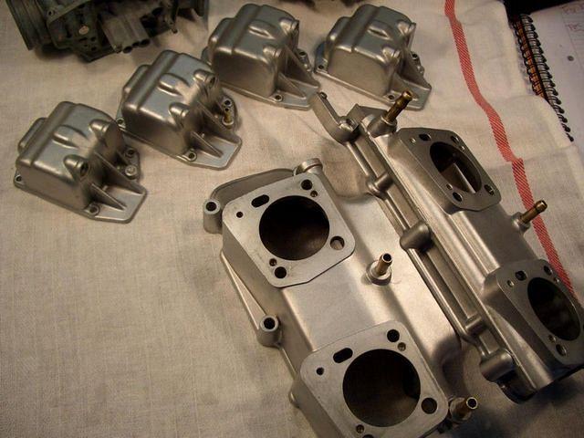
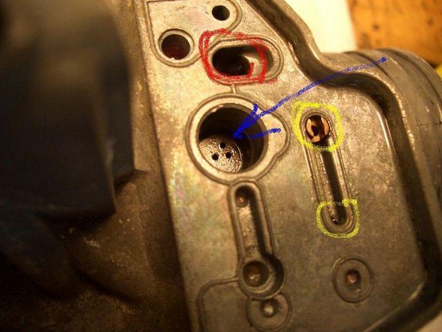
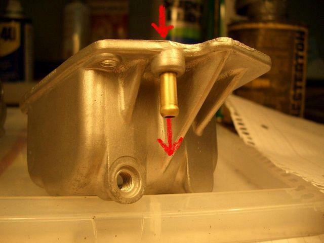
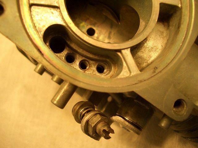
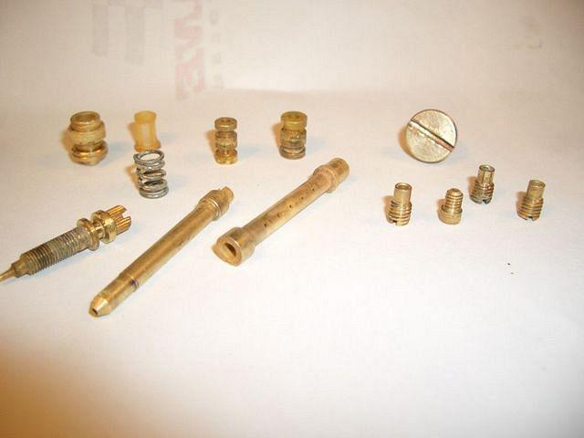
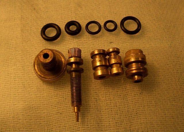
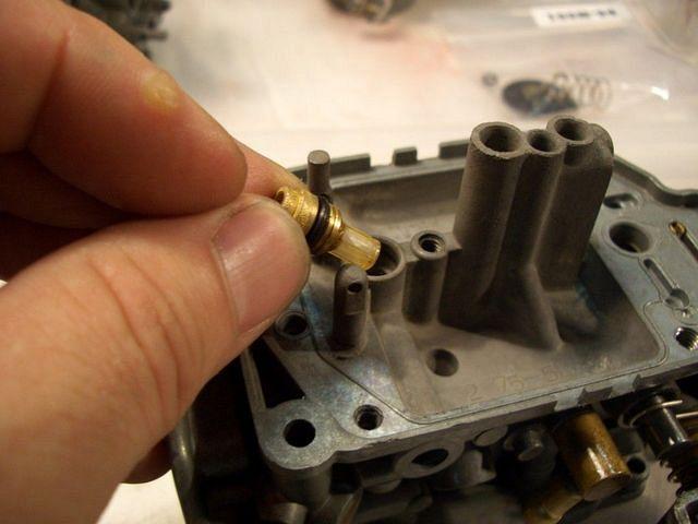
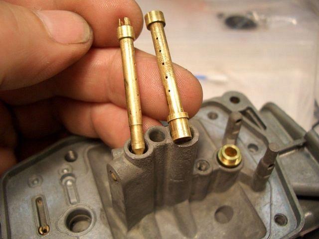
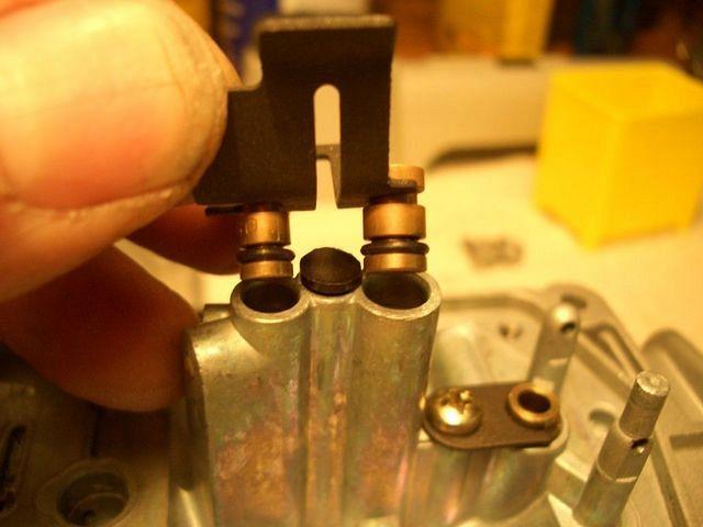
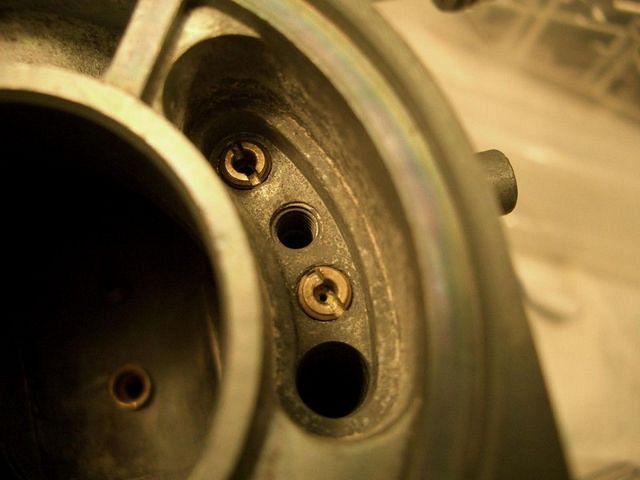
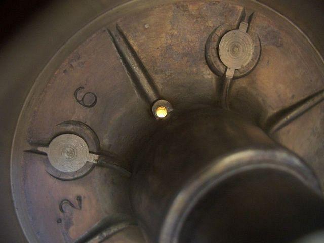
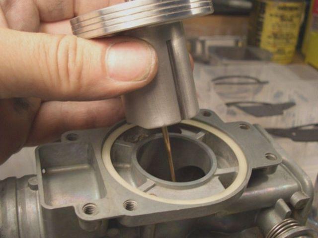
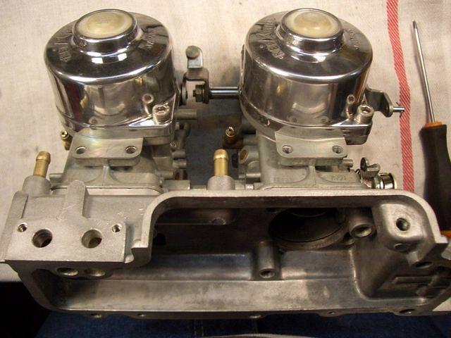
Remove primary and secondary main jets

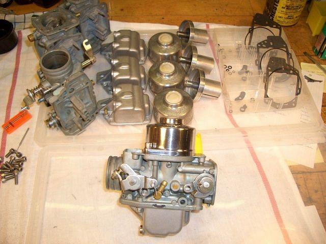
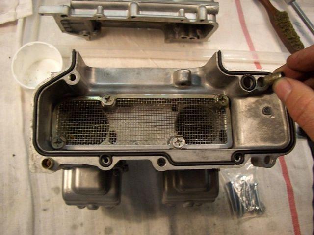
(forgot to take picture so this is an 'installation' pic.
New o-rings and all)
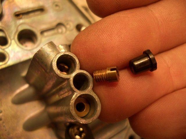
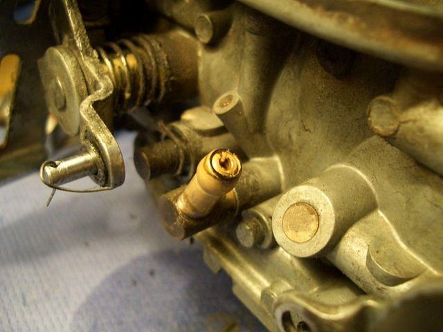
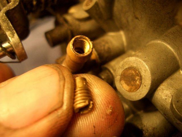
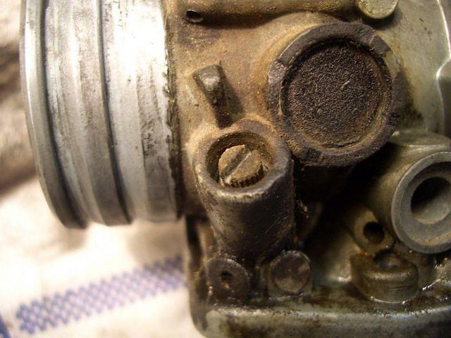
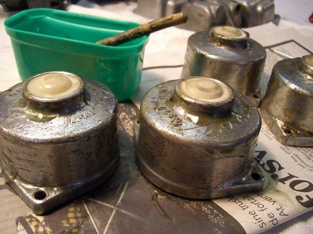
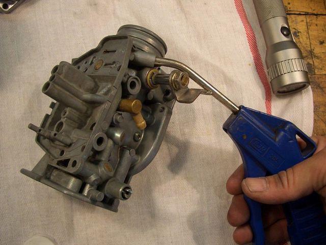
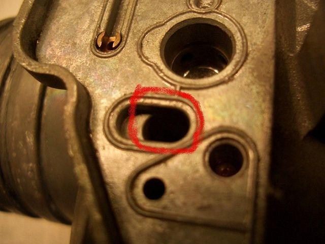
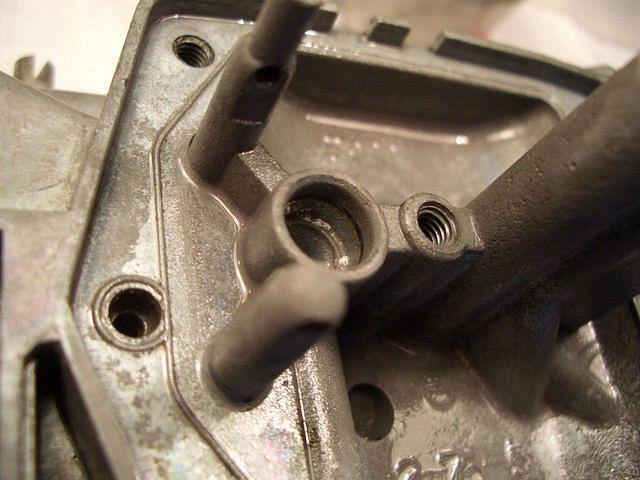
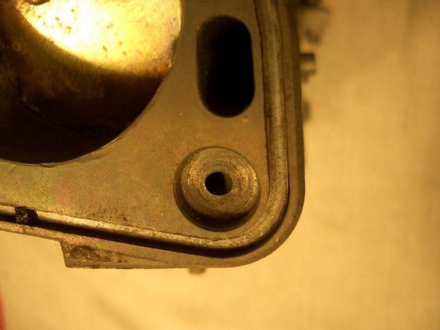
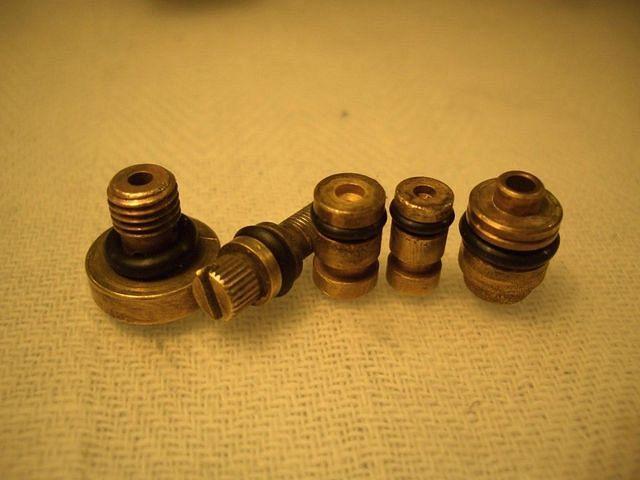
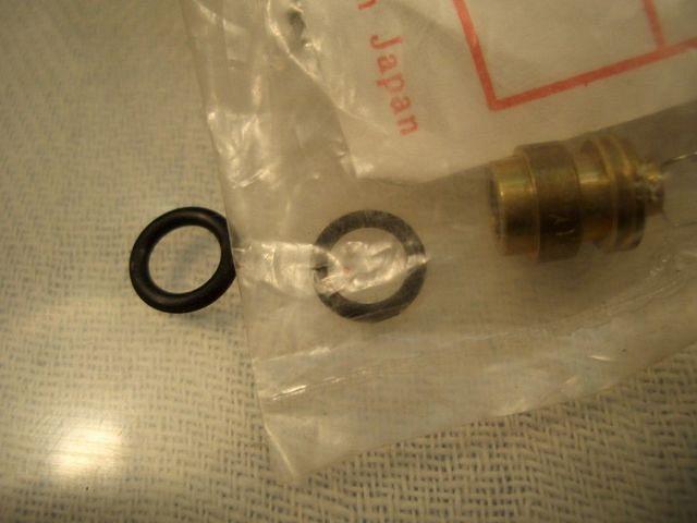
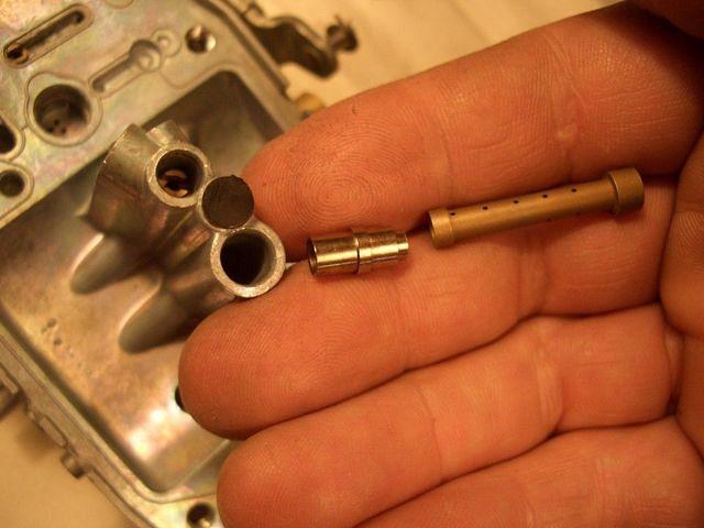
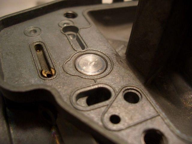
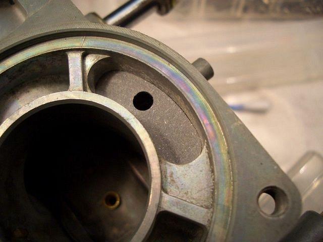
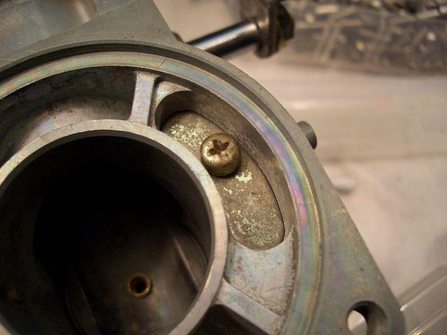
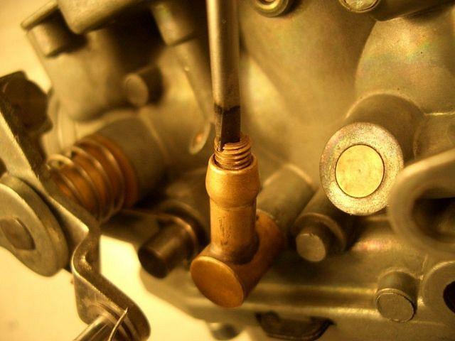
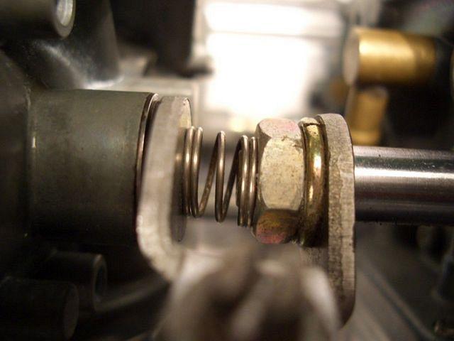
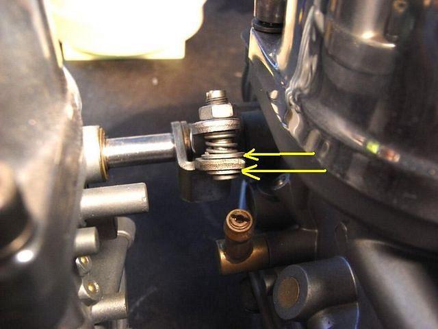
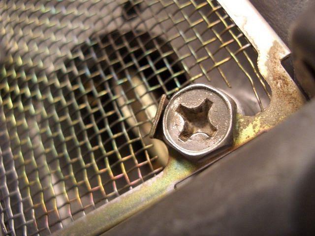
Remove fuel inlet/filter screen holder

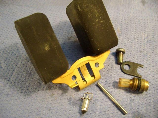
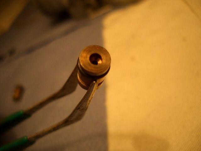
have a long good look at the state they're in:

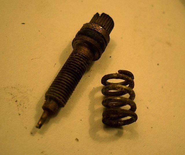
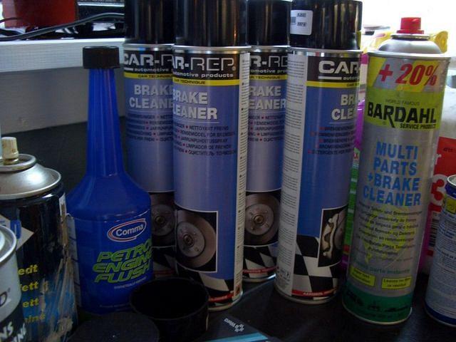
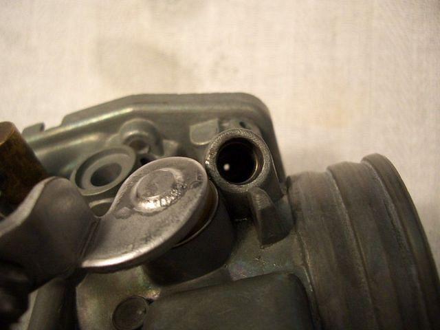
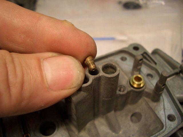
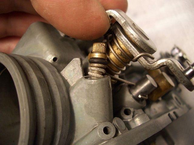
The float needles-- look on the black tit--clean it with contact cleaner or carb cleaner. Use some sort of lint-less rag to dry it off. With a magnifing glass carefully inspect the black tit for any ring around the middle. If there is a ring then it should be replaced. Ideally the SEAT should also be replaced....[snip]... Also check the spring return on the other end. It should push in and out with spring tension pushing it back out. If stuck then replace the valve.
( From Ray Wooldridge )
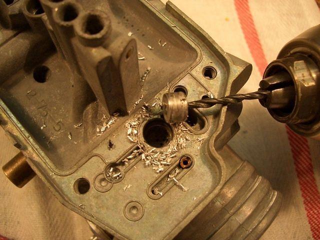
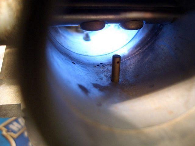
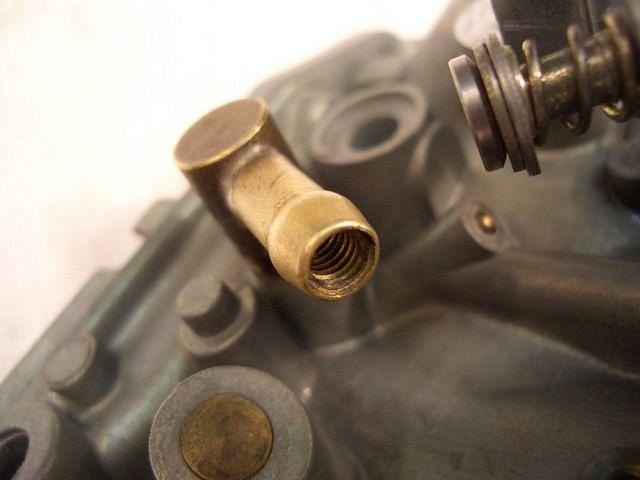
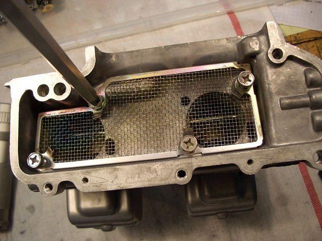
If the screen is broken; order a new one.
If it's really messed up; order a new one.
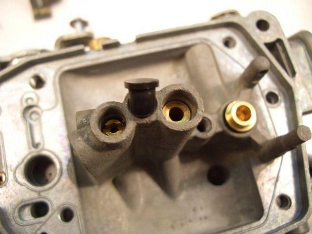
Chuck Kichline calls them
"Your hidden enemy.
There's a tiny fuel filter behind every float valve seat.
I had one plug up and cause dropout at higher speeds"
The inlet screen/seat/needle assembly is still available.
Part # 16011-371-305.
15-20$