But I understand the need, there is only a little bit of scattered info on this, most of it buried deep in threads.
So rather than muck up my build thread with more fork info, or my friend AMS's thread with any more bearing cup info I am starting a new one as a resource.
I've been asked a lot of the same questions but just recently I've been having a nice PM discussion with Bert on here who has enough of a grasp on the technical side of things to make it an easy conversation, more on that in a bit.
First off, This is not an easy project.
At least not the way I did it.
There are easier ways to swap a fork but at the sacrifice of geometry.
Stop asking me if I can make it easier, if I could I would have done it that way.
This takes technical proficiency, access to big machines, the ability to measure, if you don't own a good set of dial calipers, this will be difficult to do.
Now that's out of the way, here is some of the long drawn out info:
My build:
http://ngwclub.com/forum/viewtopic.php?f=16&t=19069
Forks start on page 3.
My friends build:
http://ngwclub.com/forum/viewtopic.php?f=16&t=30495
And the start of Berts project, you have him to thank for the rest of the info since I would not have put it together if it hadn't been nice talking to him.
http://ngwclub.com/forum/viewtopic.php? ... 0865&hilit
Below is my conversation with Bert so far, if you are serious about the swap, take the time to read this, there is some good info in there:
Bert wrote:First, congratulations on "Bike of the Month"
I am going to look at a BUSA front-end tomorrow. I feel sure it will adapt. I'm curious as to why you made a top bearing cup on your wicked bike. Why did you? Was the Suzuki stem too long or is the GSXR bearing too large for the GWing?" The guy who has the front end says it will bolt on with the right bearings and he is a well respected bike mechanic. I have also considered pressing the steering stem out of both lower trees and swapping the Gwings stem onto the the Busa lower tree then it would be a matter of using stock (Or All Balls) Gwing bearings. What are your thoughts on this?
Bert
KMR wrote:Hey Bert,
Thanks man, and the short answer to your question is "fork length."
For the most part any front end will bolt to any bike with the right bearings or with a stem swap.
But everything is a compromise.
For me my main concern was ride height. If you look around at USD fork swaps, especially any goldwing ones, the ride height tends to be is way lower than stock, way lower than it should be.
If anything I wanted the ride height to be as high as possible for this bike, more than stock even.
Sport bike frames and head angles have a very different geometry from these old tube frames, the head itself is lower and the angle steeper so the fork tubes tend to be considerably shorter.
By machining a new bearing race and cutting the old one out I was able to lower the new top triple clamp almost 2 inches from where it would have to sit otherwise, the side result was that I could run a normal size head bearing, but that was not a decision point.
Hope that helps, these swaps are just the kind of thing that take some playing around with.
cheers,
KR
Bert wrote:KR,
Thanks for your help. I took the plunge and cut the top of the steering stem tube. Awaiting bearings to give to my machinist. After I get the top cup set (Tacked) I'll measure for the lower cup length.
I really hate bothering you but I would like some info or drawings on how you mated the 320mm rotors to your front wheel. I saw the adaptors in one of the photos you posted. I've been thinking maybe I could mate the big rotors to a cut section of the standard Honda rotors. However I noticed you had some adaptors made up.
Would you share those drawings?
Also how did you use the GSXR axle with the Honda wheel?
I'm asking all of this because I want to keep my spoked wheel up front. "A" for looks "B" for ground clearance.
Bert
KMR wrote:Hey Bert,
I got these two pms yesterday but didn't have the time to respond, sorry about that, happy to help.
So, not sure where to start, the whole front wheel thing was pretty tough and it's not something that I'm completely thrilled with.
What I did:
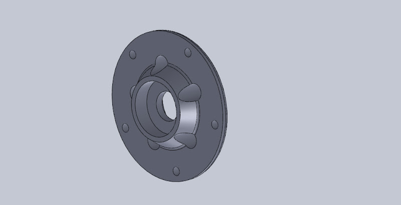
Made room for a larger axle spacer by removing some of the inner web between the OE bearing races.
Machined a new axle spacer to go between a set of new bearings.
What I did not like about this part is that the close diameter between the new axle and the OE bearing race did not allow for a very heavy duty bearing, so, I did something a little weird and got the best quality bearings I could and put two side-by-side on each side of the wheel, leaving the seal on the outside of the outermost bearing on each side but removing the others and using high quality bearing packing grease so that it could migrate between the two bearings and help spread the load and heat between the two. I have had zero problems with this and zero heat build up, but I still don't like it.
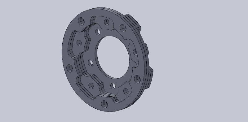
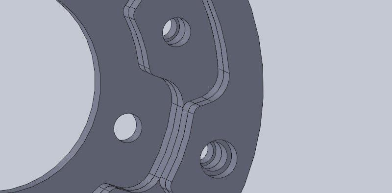
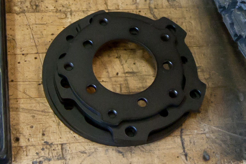
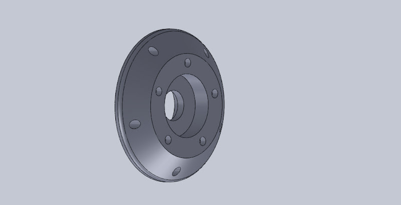
For the brakes I drew up those spacers you see (many times over to get them just right) and had them laser cut (many times over to get them right... :-b) they stack in a series of I think 4 on each side of different metal thicknesses to get the overall spacing just right and allow for the collar on the GSXR bolt to seat. The first plate is through bolted to the wheel like the OE brake rotors and the successive ones are either bolted to the previous plate with threaded holes or through bolted, then I tapped for the the GSXR rotor bolts. I have a CAD of the whole thing together that I can probably send to you later.
This also works fine, but it is rather embarrassing since it is SOOOO freaking heavy and adds a lot of weight to the wheel. (lasers can for the most part only cut steel, aluminum would have been an obvious answer but you have to have that water jet cut or milled, both of which are considerably more expensive. The weight seems like it should be a problem, but to tell the truth the front end handles and works great as is, so........
What I should have done:
I should have made one large aluminum spacer to bolt to each side using longer through bolts in the OE rotor location that would then have the bolt holes for the GSXR rotors on the outside and a new bearing race in the middle for an appropriate sized bearing. Not sure why I didn't think of that before.
It would have to be a machined part but I have access to the tools.
Hopefully that made some sense.
Time is short right now but if get a chance latter I can send you the model of what I did and since I have all the dimensions I can make another model to show what I should have done, but to tell the truth I think just making, or having made, or finding an appropriate front hub for a wire wheel and lacing a wheel on there so I can get the rim sizes I want is a better idea. (I regularly see Ducati and MotoGuzzi front spoke wheels with double rotors)
cheers,
KR
Bert wrote:If you would shoot me the drawings I believe I can get the adaptors made in T6 plate. I have a buddy with a FADAL maching center and he knows how to use it if I provide the numbers. Or Headman Headers is 20 miles from me and they have a water jet and owe me a favor.
Everything you've written makes perfect sense to me. I agree that hoging out the center bore on the Honda wheel is iffy and using smaller bearings. I wonder if having a custom axle would be the way to go. Or welding the ends of the Honda axle to make them large enough to use the Busa pinch bolts on the end of the tubes. Also custom spacers to center the wheel.
Do you think a customized Honda axle is the way to go or just have a custom axle from scratch be the way to go?
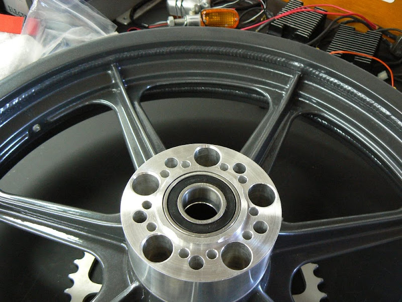
Bert
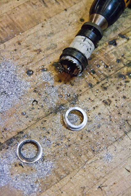
Here is an image of the aftermath of the "hogging out" for the larger axle spacer, you can see the black plastic collar around the hole saw that keeps it centered in the wheel.KMR wrote:Sorry for the delay Bert....
Haven't had a chance to get into my CAD machine and get the flies yet.
Sounds like you wont have a problem getting the parts out of aluminum, so in that case they would work out great.
As long as:
The rotor bolt pattern is the same on your 1000 as on my 1100 and on your Busa as on my GSXR. (you could pick up a set of GSXR rotors if needed though.
Also, the rotor spacing (between the rotors) would need to be the same as on both my bikes as well.
Part of the complication of the spacers was getting the right combination of material thickness for each plate so that they spaced properly.
I also found that when I made the spacers for the axle I made them equal on each side and the center for the front 1100 wheel was actually offset because of the speedo drive, I ended up having to run the wheel backwards, just something to watch out for.
I did not find that "hogging out the honda center" was worrisome at all. It is just an internal web that is there to hold the inner axle spacer roughly in line with the bearing, all I did was make a spacer to keep a hole saw centered in the hole and removed about .1875 of material, not even a second thought about that.
I like using the larger axle, but there is some merit to just saving the Honda one. I don't see how what you mentioned about welding the ends would work though, the axle still needs to pass through the bearings.
One thing that I considered would be to make precision machined shaft collars that would slip over the ends and have a couple tiny set screws to lock them in place. This should work just fine, but I think the Honda axle was shorter than what was needed for the USD front end and I didn't feel comfortable spacing it like that.
As I said, technically it should work just fine, but it adds more work and the only thing it gains you is easy bearing choice. If you had a custom axle made that was the right length, you would still need a shaft collar on at least one end so that the other could slide through the old smaller bearings.
And once again, more work, only gain is the bearings.
Will get you some drawings.
KR
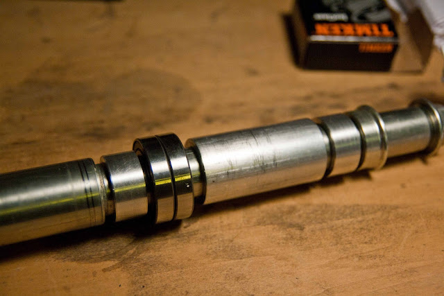
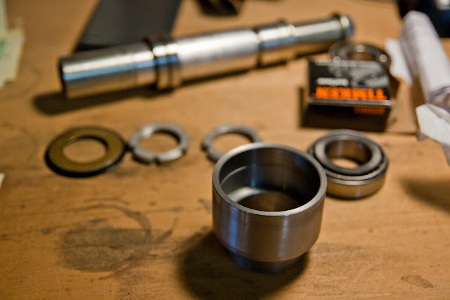
And here is the new axle spacers and two of the four new bearings.
Bert wrote: I believe the Honda axle is threaded on one end. So if you built up the non-threaded end and the threaded end it would work because once the threaded end was removed the axle could and would slide into place through the bearings before you installed the threaded end. But, a BIG BUT, if you say the Honda axle is not long enough. Then that will not work. I suppose I could have an axle turned so as to use the Honda size bearings with a fat end and a fat threaded end to slip into the pinch bolts of the Busa fork ends. In fact that may be easier than re-working the Honda axle. I'll study on it some more.
Thanks, Bert
And here is what we've covered in Angus's thread so far:
AMS wrote:I will definately send you the drawings I made up for the cups. The bearings I used are exactly as you say. My GSXR fork came with ball bearings though so I switched to the tappered roller type. The upper clamp came from a 2005 GSXR 1000 so I would have a more symetrical upper vs. the 06 - 07 upper which has the ignition off to the left. Both are interchangeable I found out. I'm still waiting for my lower bearing cup to be made but once I get that set I will send you all that you ask for Bert.Bert wrote: I will assume that you are using 30mm x 55mm x 17mm GSXR steering stem bearings. If those are what you are using would you mind sending me a copy of the drawings you made up so I may get some made as well. I'm installing basically the same front end as you are. So if you don't mind give me the specs as to how tall the bottom and top cups are as well.
Just say yes and I'll PM you my address.
Thanks, Bert
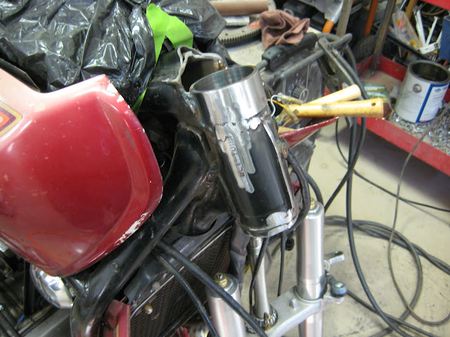
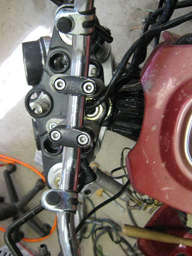
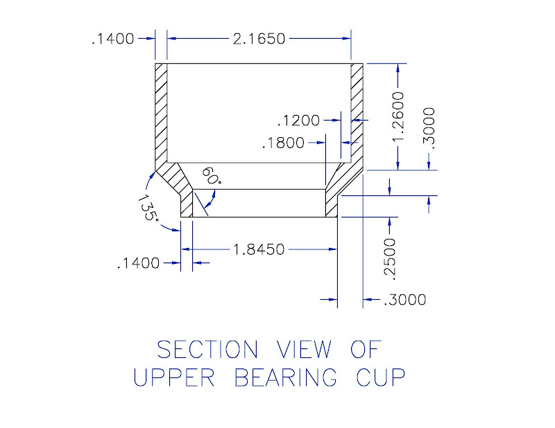
The finished bearing cup that I made:KMR wrote:Bert sent me a PM for head bearing drawings as well, along with a few others.
I'll post mine here, put up the one you used as well Angus, can split the differences that way.
I can send a solid model if anyone wants to have it run in a CNC machine as well, if you are having a part made, ask if the shop wants that, for a simple part like this some shops would just run it on a CNC these days, and would then charge you for making the file.
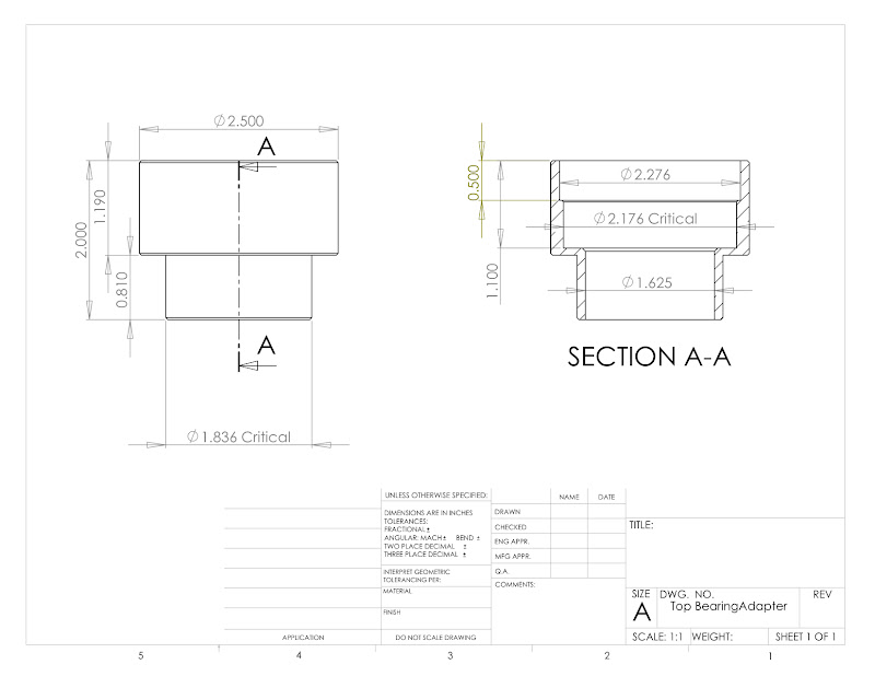
The interior height dimensions were not arbitrary, I measured my specific lock-nuts and washers to space the dust seal on the chamfer at the top.
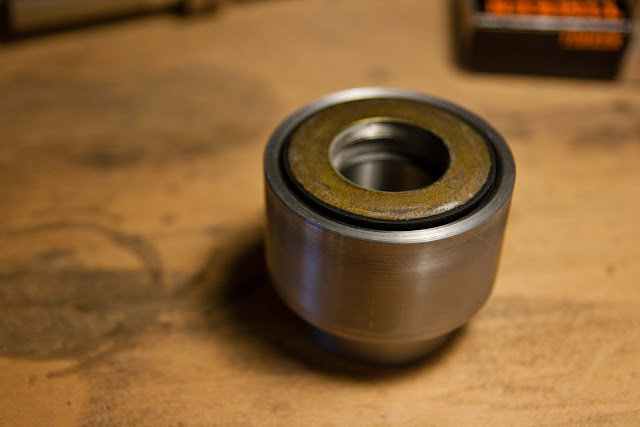
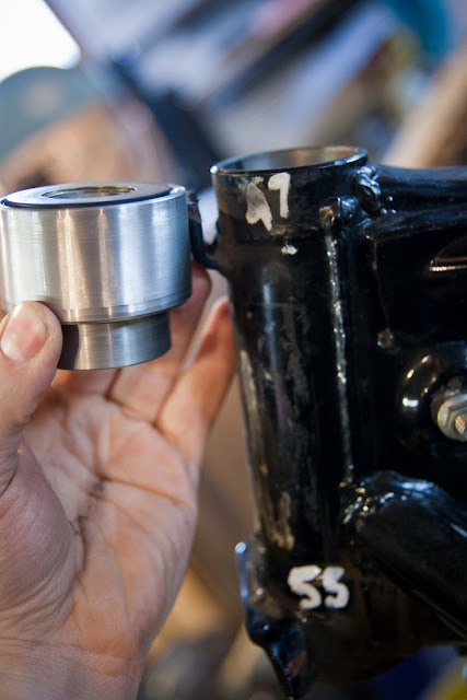
And awaiting it's new home, there are more photos in my build thread.
KMR wrote:Yeah, that'll be cool, something different.
I drag the belly from time to time jumping curbs and rocks and such, even though it's already higher than stock.
I did a rough check in the garage and straight line from the bottom frame rail the rear axle center is about 1.75 above that line, that was as high as I felt going with the motor level and drive angle considered.
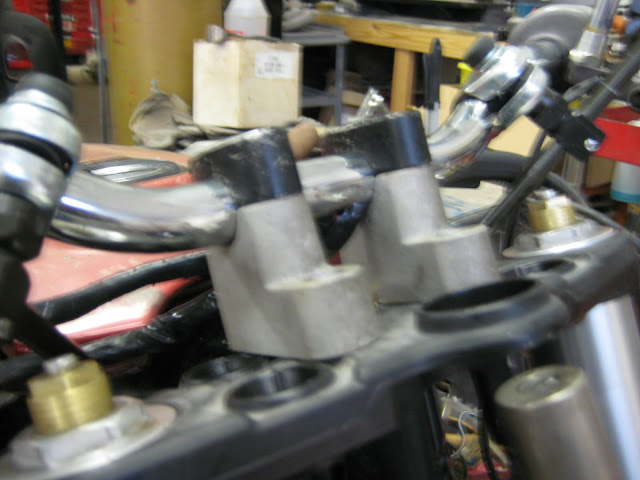
I like how you cut the top off the center stamped frame rail for the head tube as well, that will get your top clamp another .625 lower, every bit counts.
I left that bit on mine.
Both those things relate to ride height, and on the same subject I mounted the Firestones back up and have been running them, the huge aspect ratio helps lift the whole thing up a bit, especially on the front, steering angle is better with them.
I just don't push as hard in the corners, so they are safer too. :-b
If we get the wire wheel hubs sorted out neither of us will have a problem since we can just run a 17 in the back and have proper tires to choose from.
AMS wrote: I should be sending out the Info and front rotor to Rad Manufacturing to see if they can help me out with a hub this week so hopefully that solves that issue. I have the parts for the rear hub drawn and I just need to print a template to make sure it fits. I'm thinking of going 17" front and back but that changes day to day. I'm thinking of running the Battle Wings 140/80 17's both front and back I just love that tire so its hard for me to change should make for a 25-13/16" dia wheel.
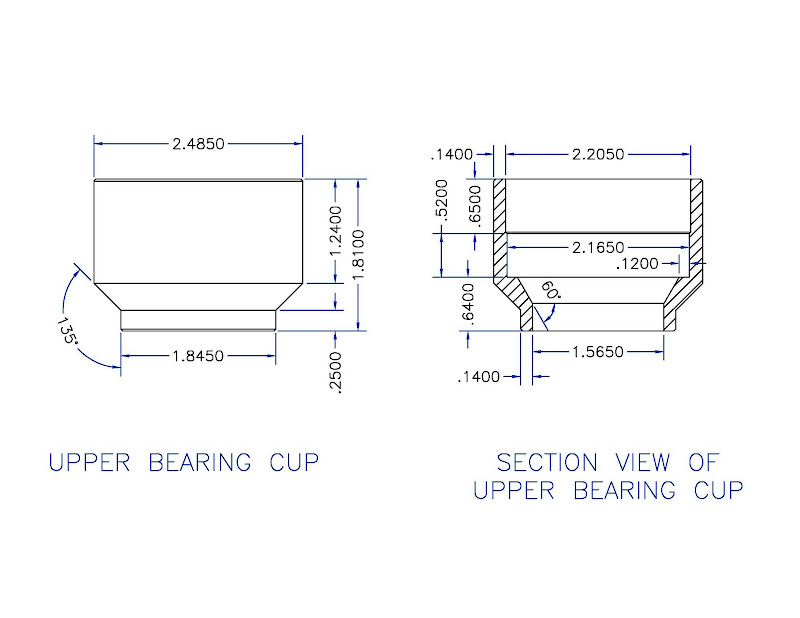
Attached is what I gave the guy who made my upper bearing cup. I basicly gave him the drawing and the bearing and he made it happen. I put that chamfer on the inside so I could get a tool in from the otherside to knock out the race in the future.
I could see no reason to keep that stamped metal there and saw that I could drop the fork a bit further also I was just having a blast with the cutoff wheel
Bert wrote:Thanks to both of you guys for the info. I really appreciate it.
Should I assume that the lower cup will be the same as the top cup?
Or will it be slightly longer where it slides into the existing steering tube for adjustment before welding?
AMS wrote:It depends on how you want to do this KMR didn't need a lower Cup because he maintained the spacing he needed to tighten down the steertube on the fork which I think is like 7" so he just kept the lower part stock. Because I cut down deeper on my frame's head tube to drop my fork down further I ran out of thread on my Fork so I need to extend down about 1" so the answer is no it will not be the same. I'm making the lower cup so it fits into the space where the stock bearing race was and then extend down a new home for the bearing race. once I get it made and put in i will feel comfortable extending that information to here so that I know it will work as I intended. I should have it build by next week I just need to find time to drop by the machine shop.
KMR wrote:I like how you angled the collar between the upper and lower portions.
You cut the steer tube down further than I did and that left room for the taper, on mine I only had room for a shallow chamfer, just enough to get a punch on the race from below. I could have cut of the steer tube off but I would have lost some VIN numbers. :-b
But, I like how I stepped the bearing race, only the bottom portion is a press-fit, with the extra clearance on the top the race is much easier to remove/install.
Combine the two and you would have a pretty good bearing race!
AMS wrote:I would definatly step it like you did for the ease of install and removal were I to do it again.
There was some Numeric casulties durring the process I made sure to do numerous pencil rubbings and photos before I started chopping away. Which should document it well enough also I will be reinstalling the little production plate when I am done. PA DMV is much easier to deal with than NY either way I'm not too worried all I will be doing is registration renewals anyway from here out till I move outta state.
Bert wrote:I am definitely going down with the top cup to get as much fork length as I can. I will probably be running the stock Busa front wheel unless I can mount the 320mm rotors on the GWing spoke wheel. I haven't pulled the stock wheel off of the Gwing yet to contemplate the swap over and of course the rotor spacing. I anciously await what you discover for the demensions of the lower cup.
Thanks, Bert
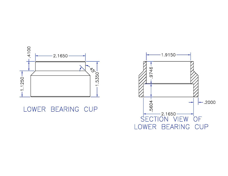
AMS wrote:Here is what I think will make a pretty dern good bearing cup.
Sorry Bert that I refuse to post the lower bearing cup yet. I can't be responsible for spreading misinformation if it fails me.
KMR got 320mm Rotors on his he had some adapters laser cut for his GL1100 wheels. Then did some messing around to get it on the GSXR axel I think. Me, I'm going for Spoked wheels all around. Saving my lunch money to afford it now.
Bert wrote:I understand where you are coming from about the lower cup length.
I just pulled my front end and used a dial bore gauge on the inside diameter. In your drawing the part of the cup that drops into the steering stem is "1.8450" when I measured mine the inside diameter is somewhat less at "1.6515". Then it occurred to me that you and KMR both have GL 1100's and my bike is a GL1000 1975 model. Honda must have increased the inside diameter on the 1100's All of the other dimensions should work
for me. I will be picking up my tapered bearings tomorrow and my machinist is waiting for me to bring them to him so he can double check everything. I'll tell him about the difference in the diameter before he starts on them. I'm going to have him make the lower cup drop in portion longer than I think I'll need as he offered to cut it for free if it's too long. I believe that if I mount the upper cup tack it and put the lower cup on and bolt it up the the front end the lower cup will sit at whatever depth it needs to be. Then I'll tack it and pull the stem and weld it up. Then re-assemble.
AMS wrote:I think that this has been discussed enough to where this is harmless to Post. This is my intended lower bearing cup the tab should fit into the space for the old lower bearing in the stem which on the GL1100 I know is a 55mm bearing. really the only thing I'm holding on is if this is to long but if it is its only .050 or less long. but it may be different depending on how deep you cut in your upper bearing cup into the stem. I hope this helps once I get this all mounted in next week I'll probably post a drawing showing all the spacing and relationship between the two cups.
Bert wrote:I had the same thought about the lower as far as making the cup fit the existing bearing race relief. I mustered up some cajones and went ahead and made the cut before receiving the part. I'm confident it will work out fine. Once I set the upper cup I can then measure the lower cup dimensions.
Again thank you for helping me.
Bert
And that is where things stand.
The pertinent info we've posted is now here, more to come.
If you know of any other good information post it here as well and it should make everything a good bit smoother.